
Diesel locomotive
This article needs additional citations for verification. (December 2019) |
.jpg)

A diesel locomotive is a type of
Early
The first successful diesel engines used
The economic recovery from World War II hastened the widespread adoption of diesel locomotives in many countries. They offered greater flexibility and performance than steam locomotives, as well as substantially lower operating and maintenance costs.[8]
History
Adaptation for rail use


The earliest recorded example of the use of an internal combustion engine in a railway locomotive is the prototype designed by
Rudolf Diesel considered using his engine for powering locomotives in his 1893 book Theorie und Konstruktion eines rationellen Wärmemotors zum Ersatz der Dampfmaschine und der heute bekannten Verbrennungsmotoren (Theory and Construction of a Rational Heat Motor).[14] However, the large size and poor power-to-weight ratio of early diesel engines made them unsuitable for propelling land-based vehicles. Therefore, the engine's potential as a railroad prime mover was not initially recognized.[15] This changed as research and development reduced the size and weight of the engine.
In 1906, Rudolf Diesel, Adolf Klose and the steam and diesel engine manufacturer Gebrüder Sulzer founded Diesel-Sulzer-Klose GmbH to manufacture diesel-powered locomotives. Sulzer had been manufacturing diesel engines since 1898. The Prussian State Railways ordered a diesel locomotive from the company in 1909, and after test runs between Winterthur and Romanshorn, Switzerland, the diesel–mechanical locomotive was delivered in Berlin in September 1912. The world's first diesel-powered locomotive was operated in the summer of 1912 on the same line from Winterthur but was not a commercial success.[16] During test runs in 1913 several problems were found. The outbreak of World War I in 1914 prevented all further trials. The locomotive weight was 95 tonnes and the power was 883 kW (1,184 hp) with a maximum speed of 100 km/h (62 mph).[17]
Small numbers of prototype diesel locomotives were produced in a number of countries through the mid-1920s.
Early diesel locomotives and railcars in Asia
China
One of the first domestically developed Diesel vehicles of China was the
India
Japan
In Japan, starting in the 1920s, some petrol–electric railcars were produced. The first diesel–electric traction and the first air-streamed vehicles on Japanese rails were the two DMU3s of class Kiha 43000 (キハ43000系).[18] Japan's first series of diesel locomotives was class DD50 (国鉄DD50形), twin locomotives, developed since 1950 and in service since 1953.[19]
Early diesel locomotives and railcars in Europe
First functional diesel vehicles

In 1914, the world's first functional diesel–electric railcars were produced for the Königlich-Sächsische Staatseisenbahnen (
Fiat claims to have built the first Italian diesel–electric locomotive in 1922, but little detail is available. Several Fiat-TIBB Bo'Bo' diesel–locomotives were built for service on the 950 mm (3 ft 1+3⁄8 in) narrow gauge Ferrovie Calabro Lucane and the Società per le Strade Ferrate del Mediterrano in southern Italy in 1926, following trials in 1924–25.[20] The six-cylinder two-stroke motor produced 440 horsepower (330 kW) at 500 rpm, driving four DC motors, one for each axle. These 44 tonnes (43 long tons; 49 short tons) locomotives with 45 km/h (28 mph) top speed proved quite successful.[21]
In 1924, two diesel–electric locomotives were taken in service by the Soviet railways, almost at the same time:
- The engine Ээл2 (Yuri Lomonosov and built 1923–1924 by Maschinenfabrik Esslingen in Germany. It had five driving axles (1'E1'). After several test rides, it hauled trains for almost three decades from 1925 to 1954.[22]It became a model for several classes of Soviet diesel locomotives.
- The engine Щэл1 (Shch-el 1, original number Юэ2/Yu-e 2), started on November 9. It had been developed by Yakov Modestovich Gakkel and built by Baltic Shipyard in Saint Petersburg. It had ten driving axles in three bogies (1' Co' Do' Co' 1'). From 1925 to 1927, it hauled trains between Moscow and Kursk and in Caucasus region. Due to technical problems, afterwards, it was out of service. Since 1934, it was used as a stationary electric generator.
In 1935,
, in Germany. Diesel–hydraulics became the mainstream in diesel locomotives in Germany since the German railways (DRG) were pleased with the performance of that engine. Serial production of diesel locomotives in Germany began after World War II.Switchers

In many railway stations and industrial compounds, steam shunters had to be kept hot during many breaks between scattered short tasks. Therefore, diesel traction became economical for shunting before it became economical for hauling trains. The construction of diesel shunters began in 1920 in France, in 1925 in Denmark, in 1926 in the Netherlands, and in 1927 in Germany. After a few years of testing, hundreds of units were produced within a decade.
Diesel railcars for regional traffic

Diesel-powered or "oil-engined" railcars, generally diesel–mechanical, were developed by various European manufacturers in the 1930s, e.g. by
High-speed railcars
In the 1930s, streamlined highspeed diesel railcars were developed in several countries:
- In Germany, the Flying Hamburger was built in 1932. After a test ride in December 1932, this two-coach diesel railcar (in English terminology a DMU2) started service at Deutsche Reichsbahn (DRG) in February 1933. It became the prototype of DRG Class SVT 137with 33 more highspeed DMUs, built for DRG till 1938, 13 DMU 2 ("Hamburg" series), 18 DMU 3 ("Leipzig" and "Köln" series), and two DMU 4 ("Berlin" series).
- French SNCF classes XF 1000 and XF 1100 comprised 11 high-speed DMUs, also called TAR, built 1934–1939.
- In Hungary, Ganz Works built the Arpád railmotor, a kind of a luxurious railbus in a series of seven items since 1934 and started to build the Hargita in 1944.
Further developments

In 1945, a batch of 30 Baldwin diesel–electric locomotives, Baldwin 0-6-6-0 1000, was delivered from the United States to the railways of the Soviet Union.
In 1947, the London, Midland and Scottish Railway (LMS) introduced the first of a pair of 1,600 hp (1,200 kW) Co-Co diesel–electric locomotives (later British Rail Class D16/1) for regular use in the United Kingdom, although British manufacturers such as Armstrong Whitworth had been exporting diesel locomotives since 1930. Fleet deliveries to British Railways, of other designs such as Class 20 and Class 31, began in 1957.
Series production of diesel locomotives in Italy began in the mid-1950s. Generally, diesel traction in Italy was of less importance than in other countries, as it was amongst the most advanced countries in the electrification of the main lines and as Italian geography makes freight transport by sea cheaper than rail transportation even on many domestic connections.
Early diesel locomotives and railcars in North America
Early North American developments
Adolphus Busch purchased the American manufacturing rights for the diesel engine in 1898 but never applied this new form of power to transportation. He founded the Busch-Sulzer company in 1911. Only limited success was achieved in the early twentieth century with internal combustion engined railcars, due, in part, to difficulties with mechanical drive systems.[23]
A significant breakthrough occurred in 1914, when Hermann Lemp, a GE electrical engineer, developed and patented a reliable control system that controlled the engine and traction motor with a single lever; subsequent improvements were also patented by Lemp.[25] Lemp's design solved the problem of overloading and damaging the traction motors with excessive electrical power at low speeds, and was the prototype for all internal combustion–electric drive control systems.
In 1917–1918, GE produced three experimental diesel–electric locomotives using Lemp's control design, the first known to be built in the United States.[26] Following this development, the 1923 Kaufman Act banned steam locomotives from New York City, because of severe pollution problems. The response to this law was to electrify high-traffic rail lines. However, electrification was uneconomical to apply to lower-traffic areas.
The first regular use of diesel–electric locomotives was in
In June 1925,
Before diesel power could make inroads into mainline service, the limitations of diesel engines circa 1930 – low power-to-weight ratios and narrow output range – had to be overcome. A major effort to overcome those limitations was launched by
Diesel–electric railroad locomotion entered mainline service when the
First American series production locomotives
Following their 1925 prototype, the AGEIR consortium produced 25 more units of 300 hp (220 kW) "60 ton"
GM, seeing the success of the custom streamliners, sought to expand the market for diesel power by producing standardized locomotives under their
Following the successful 1939 tour of
In the early postwar era, EMD dominated the market for mainline locomotives with their E and F series locomotives. ALCO-GE in the late 1940s produced switchers and road-switchers that were successful in the short-haul market. However, EMD launched their GP series road-switcher locomotives in 1949, which displaced all other locomotives in the freight market including their own F series locomotives. GE subsequently dissolved its partnership with ALCO and would emerge as EMD's main competitor in the early 1960s, eventually taking the top position in the locomotive market from EMD.
Early diesel–electric locomotives in the United States used direct current (DC) traction motors but alternating current (AC) motors came into widespread use in the 1990s, starting with the Electro-Motive SD70MAC in 1993 and followed by General Electric's AC4400CW in 1994 and AC6000CW in 1995.[37]
Early diesel locomotives and railcars in Oceania

The Trans-Australian Railway built 1912 to 1917 by Commonwealth Railways (CR) passes through 2,000 km of waterless (or salt watered) desert terrain unsuitable for steam locomotives. The original engineer Henry Deane envisaged diesel operation to overcome such problems.[38] Some have suggested that the CR worked with the South Australian Railways to trial diesel traction.[39] However, the technology was not developed enough to be reliable.
As in Europe, the usage of internal combustion engines advanced more readily in self-propelled railcars than in locomotives:
- Some Australian railway companies bought McKeen railmotors.
- In the 1920s and 1930s, more reliable Gasoline railmotors were built by Australian industries.
- Australia's first diesel railcars were the NSWGR 100 Class (PH later DP) Silver City Comet cars in 1937.[40]
- High-speed vehicles for those days' possibilities on 3 ft 6 in (1,067 mm) were the ten Vulcan railcars of 1940 for New Zealand.
Transmission types
Diesel–mechanical

A diesel–mechanical locomotive uses a
The mechanical transmissions used for railroad propulsion are generally more complex and much more robust than standard-road versions. There is usually a fluid coupling interposed between the engine and gearbox, and the gearbox is often of the epicyclic (planetary) type to permit shifting while under load. Various systems have been devised to minimise the break in transmission during gear changing, e.g., the S.S.S. (synchro-self-shifting) gearbox used by Hudswell Clarke.
Diesel–mechanical propulsion is limited by the difficulty of building a reasonably sized transmission capable of coping with the power and torque required to move a heavy train. A number of attempts to use diesel–mechanical propulsion in high power applications have been made (e.g., the 1,500 kW (2,000 hp) British Rail 10100 locomotive), though only few have proven successful (such as the 1,342 kW (1,800 hp) DSB Class MF).
Diesel–electric


.jpg)
In a diesel–electric locomotive, the diesel engine drives either an electrical DC generator (generally, less than 3,000 hp (2,200 kW) net for traction), or an electrical AC alternator-rectifier (generally 3,000 hp net or more for traction), the output of which provides power to the traction motors that drive the locomotive. There is no mechanical connection between the diesel engine and the wheels.
The important components of diesel–electric propulsion are the diesel engine (also known as the

Originally, the traction motors and generator were
Current North American practice is for four axles for high-speed passenger or "time" freight, or for six axles for lower-speed or "manifest" freight. The most modern units on "time" freight service tend to have six axles underneath the frame. Unlike those in "manifest" service, "time" freight units will have only four of the axles connected to traction motors, with the other two as idler axles for weight distribution.
In the late 1980s, the development of high-power variable-voltage/variable-frequency (VVVF) drives, or "traction inverters", allowed the use of polyphase AC traction motors, thereby also eliminating the motor commutator and brushes. The result is a more efficient and reliable drive that requires relatively little maintenance and is better able to cope with overload conditions that often destroyed the older types of motors.
Diesel–electric control

A diesel–electric locomotive's power output is independent of road speed, as long as the unit's generator current and voltage limits are not exceeded. Therefore, the unit's ability to develop
Throttle operation


The prime mover's power output is primarily determined by its rotational speed (RPM) and fuel rate, which are regulated by a governor or similar mechanism. The governor is designed to react to both the throttle setting, as determined by the engine driver and the speed at which the prime mover is running (see Control theory).
Locomotive power output, and therefore speed, is typically controlled by the engine driver using a stepped or "notched"
North American locomotives, such as those built by EMD or General Electric, have eight throttle positions or "notches" as well as a "reverser" to allow them to operate bi-directionally. Many UK-built locomotives have a ten-position throttle. The power positions are often referred to by locomotive crews depending upon the throttle setting, such as "run 3" or "notch 3".
In older locomotives, the throttle mechanism was ratcheted so that it was not possible to advance more than one power position at a time. The engine driver could not, for example, pull the throttle from notch 2 to notch 4 without stopping at notch 3. This feature was intended to prevent rough train handling due to abrupt power increases caused by rapid throttle motion ("throttle stripping", an operating rules violation on many railroads). Modern locomotives no longer have this restriction, as their control systems are able to smoothly modulate power and avoid sudden changes in train loading regardless of how the engine driver operates the controls.
When the throttle is in the idle position, the prime mover receives minimal fuel, causing it to idle at low RPM. In addition, the traction motors are not connected to the main generator and the generator's field windings are not excited (energized) – the generator does not produce electricity without excitation. Therefore, the locomotive will be in "neutral". Conceptually, this is the same as placing an automobile's transmission into neutral while the engine is running.
To set the locomotive in motion, the
Placing the throttle into the first power position will cause the traction motors to be connected to the main generator and the latter's field coils to be excited. With excitation applied, the main generator will deliver electricity to the traction motors, resulting in motion. If the locomotive is running "light" (that is, not coupled to the rest of a train) and is not on an ascending grade, it will easily accelerate. On the other hand, if a long train is being started, the locomotive may stall as soon as some of the slack has been taken up, as the drag imposed by the train will exceed the tractive force being developed. An experienced engine driver will be able to recognize an incipient stall and will gradually advance the throttle as required to maintain the pace of acceleration.
As the throttle is moved to higher power notches, the fuel rate to the prime mover will increase, resulting in a corresponding increase in RPM and horsepower output. At the same time, main generator field excitation will be proportionally increased to absorb the higher power. This will translate into increased electrical output to the traction motors, with a corresponding increase in tractive force. Eventually, depending on the requirements of the train's schedule, the engine driver will have moved the throttle to the position of maximum power and will maintain it there until the train has accelerated to the desired speed.
The propulsion system is designed to produce maximum traction motor torque at start-up, which explains why modern locomotives are capable of starting trains weighing in excess of 15,000 tons, even on ascending grades. Current technology allows a locomotive to develop as much as 30% of its loaded driver weight in tractive force, amounting to 120,000 pounds-force (530 kN) of
Propulsion system operation


A locomotive's control system is designed so that the main generator
In older designs, the prime mover's governor and a companion device, the load regulator, play a central role in the control system. The governor has two external inputs: requested engine speed, determined by the engine driver's throttle setting, and actual engine speed (

As the load on the engine changes, its rotational speed will also change. This is detected by the governor through a change in the engine speed feedback signal. The net effect is to adjust both the fuel rate and the load regulator position so that engine RPM and torque (and therefore power output) will remain constant for any given throttle setting, regardless of actual road speed.
In newer designs controlled by a "traction computer," each engine speed step is allotted an appropriate power output, or "kW reference", in software. The computer compares this value with actual main generator power output, or "kW feedback", calculated from traction motor current and main generator voltage feedback values. The computer adjusts the feedback value to match the reference value by controlling the excitation of the main generator, as described above. The governor still has control of engine speed, but the load regulator no longer plays a central role in this type of control system. However, the load regulator is retained as a "back-up" in case of engine overload. Modern locomotives fitted with
Traction motor performance is controlled either by varying the DC voltage output of the main generator, for DC motors, or by varying the frequency and voltage output of the VVVF for AC motors. With DC motors, various connection combinations are utilized to adapt the drive to varying operating conditions.
At standstill, main generator output is initially low voltage/high current, often in excess of 1000 amperes per motor at full power. When the locomotive is at or near standstill, current flow will be limited only by the DC resistance of the motor windings and interconnecting circuitry, as well as the capacity of the main generator itself. Torque in a series-wound motor is approximately proportional to the square of the current. Hence, the traction motors will produce their highest torque, causing the locomotive to develop maximum tractive effort, enabling it to overcome the inertia of the train. This effect is analogous to what happens in an automobile automatic transmission at start-up, where it is in first gear and thereby producing maximum torque multiplication.
As the locomotive accelerates, the now-rotating motor armatures will start to generate a counter-electromotive force (back EMF, meaning the motors are also trying to act as generators), which will oppose the output of the main generator and cause traction motor current to decrease. Main generator voltage will correspondingly increase in an attempt to maintain motor power but will eventually reach a plateau. At this point, the locomotive will essentially cease to accelerate, unless on a downgrade. Since this plateau will usually be reached at a speed substantially less than the maximum that may be desired, something must be done to change the drive characteristics to allow continued acceleration. This change is referred to as "transition", a process that is analogous to shifting gears in an automobile.
Transition methods include:
- Series / Parallel or "motor transition".
- Initially, pairs of motors are connected in series across the main generator. At higher speed, motors are reconnected in parallel across the main generator.
- "Field shunting", "field diverting", or "weak fielding".
- Resistance is connected in parallel with the motor field. This has the effect of increasing the armaturecurrent, producing a corresponding increase in motor torque and speed.
- Resistance is connected in parallel with the motor field. This has the effect of increasing the
Both methods may also be combined, to increase the operating speed range.
- Generator / rectifier transition
- Reconnecting the two separate internal main generator stator windings of two rectifiers from parallel to series to increase the output voltage.
In older locomotives, it was necessary for the engine driver to manually execute transition by use of a separate control. As an aid to performing transition at the right time, the load meter (an indicator that shows the engine driver how much current is being drawn by the traction motors) was calibrated to indicate at which points forward or backward transition should take place. Automatic transition was subsequently developed to produce better-operating efficiency and to protect the main generator and traction motors from overloading from improper transition.
Modern locomotives incorporate traction inverters, AC to DC, capable of delivering 1,200 volts (earlier traction generators, DC to DC, were capable of delivering only 600 volts). This improvement was accomplished largely through improvements in silicon diode technology. With the capability of delivering 1,200 volts to the traction motors, the need for "transition" was eliminated.
Dynamic braking
A common option on diesel–electric locomotives is dynamic (rheostatic) braking.
Dynamic braking takes advantage of the fact that the
- The field winding of each traction motor is connected across the main generator.
- The armature of each traction motor is connected across a forced-air-cooled resistance grid (the dynamic braking grid) in the roof of the locomotive's hood.
- The prime mover RPM is increased, and the main generator field is excited, causing a corresponding excitation of the traction motor fields.
The aggregate effect of the above is to cause each traction motor to generate electric power and dissipate it as heat in the dynamic braking grid. A fan connected across the grid provides forced-air cooling. Consequently, the fan is powered by the output of the traction motors and will tend to run faster and produce more airflow as more energy is applied to the grid.
Ultimately, the source of the energy dissipated in the dynamic braking grid is the motion of the locomotive as imparted to the traction motor armatures. Therefore, the traction motors impose drag and the locomotive acts as a brake. As speed decreases, the braking effect decays and usually becomes ineffective below approximately 16 km/h (10 mph), depending on the gear ratio between the traction motors and axles.
Dynamic braking is particularly beneficial when operating in mountainous regions, where there is always the danger of a runaway due to overheated friction brakes during descent. In such cases, dynamic brakes are usually applied in conjunction with the
Electro-diesel
These special locomotives can operate as an
Diesel–hydraulic

Diesel–hydraulic locomotives use one or more torque converters, in combination with fixed ratio gears. Drive shafts and gears form the final drive to convey the power from the torque converters to the wheels, and to effect reverse. The difference between hydraulic and mechanical systems is where the speed and torque is adjusted. In the mechanical transmission system that has multiple ratios such as in a gear box, if there is a hydraulic section, it is only to allow the engine to run when the train is too slow or stopped. In the hydraulic system, hydraulics are the primary system for adapting engine speed and torque to the train's situation, with gear selection for only limited use, such as reverse gear.
Hydrostatic transmission
Hydraulic drive systems using a
Application of hydrostatic transmissions is generally limited to small shunting locomotives and rail maintenance equipment, as well as being used for non-tractive applications in diesel engines such as drives for traction motor fans.[citation needed]
Hydrokinetic transmission

1 — diesel, 2 — oil filter, 3 — turning gear, 4 — water-to-fuel heater, 5 — auxiliary electric generator, 6 — hydrokinetic transmission, 7 — first gear valve (with manual shift handle), 8 — automatic transmission oil filter
Hydrokinetic transmission (also called hydrodynamic transmission) uses a torque converter. A torque converter consists of three main parts, two of which rotate, and one (the stator) that has a lock preventing backwards rotation and adding output torque by redirecting the oil flow at low output RPM. All three main parts are sealed in an oil-filled housing. To match engine speed to load speed over the entire speed range of a locomotive some additional method is required to give sufficient range. One method is to follow the torque converter with a mechanical gearbox which switches ratios automatically, similar to an automatic transmission in an automobile. Another method is to provide several torque converters each with a range of variability covering part of the total required; all the torque converters are mechanically connected all the time, and the appropriate one for the speed range required is selected by filling it with oil and draining the others. The filling and draining is carried out with the transmission under load, and results in very smooth range changes with no break in the transmitted power.
-
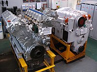 Diesel prime mover (left) and hydraulic transmission (right) of the British Rail Class 52 diesel locomotive
 -
 South African Class 61-000 diesel-hydraulic locomotive under construction

_1.jpg)
Locomotives

Diesel-hydraulic locomotives are less efficient than diesel–electrics. The first-generation BR diesel hydraulics were significantly less efficient (c. 65%) than diesel electrics (c. 80%),[citation needed] Moreover, initial versions were found in many countries to be mechanically more complicated and more likely to break down.[citation needed] Hydraulic transmission for locomotives was developed in Germany.[citation needed] There is still debate over the relative merits of hydraulic vs. electrical transmission systems: advantages claimed for hydraulic systems include lower weight, high reliability, and lower capital cost.[citation needed]
By the 21st century, for diesel locomotive traction worldwide the majority of countries used diesel–electric designs, with diesel-hydraulic designs not found in use outside Germany and Japan, and some neighbouring states, where it is used in designs for freight work.
In Germany and Finland, diesel–hydraulic systems have achieved high reliability in operation.[
Diesel–hydraulic locomotives have a smaller market share than those with diesel–electric transmission – the main worldwide user of main-line hydraulic transmissions was the
Other main-line locomotives of the post-war period included the 1950s
In Finland, over 200 Finnish-built VR class Dv12 and Dr14 diesel–hydraulics with Voith transmissions have been continuously used since the early 1960s. All units of Dr14 class and most units of Dv12 class are still in service. VR has abandoned some weak-conditioned units of 2700 series Dv12s.[48]
In the 21st century series production standard gauge diesel–hydraulic designs include the Voith Gravita, ordered by Deutsche Bahn, and the Vossloh G2000 BB, G1206 and G1700 designs, all manufactured in Germany for freight use.
-
 JNR DD51 1 diesel-hydraulic
 -
 DB class V 200 diesel–hydraulic locomotive
 -
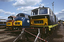 British Rail diesel–hydraulic locomotives: Class 52 "Western", Class 42 "Warship" and Class 35 "Hymek"
 -
 tA VR Class Dv12 diesel–hydraulic locomotive
 -
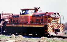 A GMD GMDH-1 diesel–hydraulic locomotive
 -
 A Soviet diesel-hydraulic locomotive TGM23


.jpg)
Multiple units
Diesel–hydraulic drive is common in multiple units, with various transmission designs used including Voith torque converters, and fluid couplings in combination with mechanical gearing.
The majority of
Diesel–steam

Steam-diesel hybrid locomotives can use steam generated from a boiler or diesel to power a piston engine. The Cristiani Compressed Steam System used a diesel engine to power a compressor to drive and recirculate steam produced by a boiler; effectively using steam as the power transmission medium, with the diesel engine being the prime mover[49]
Diesel–pneumatic
The diesel-pneumatic locomotive was of interest in the 1930s because it offered the possibility of converting existing steam locomotives to diesel operation. The frame and cylinders of the steam locomotive would be retained and the boiler would be replaced by a diesel engine driving an
Multiple-unit operation

Most diesel locomotives are capable of
The ability to couple diesel–electric locomotives in an MU fashion was first introduced in the EMC EA/EB of 1937. Electrical interconnections were made so one engine driver could operate the entire consist from the head-end unit.
In mountainous regions, it is common to interpose
Cab arrangements
Cab arrangements vary by builder and operator. Practice in the U.S. has traditionally been for a cab at one end of the locomotive with limited visibility if the locomotive is not operated cab forward. This is not usually a problem as U.S. locomotives are usually operated in pairs, or threes, and arranged so that a cab is at each end of each set. European practice is usually for a cab at each end of the locomotive as trains are usually light enough to operate with one locomotive. Early U.S. practice was to add power units without cabs (booster or
Cow-calf
_Cow_and_Calf_at_Riverside_Yard,_Baltimore_(22341847029).jpg)
In North American railroading, a
Cow-calves have largely disappeared as these engine combinations exceeded their economic lifetimes many years ago.
Present North American practice is to pair two 3,000 hp GP40-2 or SD40-2 road switchers, often nearly worn-out and very soon ready for rebuilding or scrapping, and to utilize these for so-called "transfer" uses, for which the TR-2, TR-3 and TR-4 engines were originally intended, hence the designation TR, for "transfer".
Occasionally, the second unit may have its prime-mover and traction alternator removed and replaced by concrete or steel ballast and the power for traction obtained from the master unit. As a 16-cylinder prime-mover generally weighs in the 36,000-pound (16,000 kg) range, and a 3,000 hp traction alternator generally weighs in the 18,000-pound (8,200 kg) range, this would mean that 54,000 lb (24,000 kg) would be needed for ballast.
A pair of fully capable "Dash 2" units would be rated 6,000 hp (4,500 kW). A "Dash 2" pair where only one had a prime-mover/alternator would be rated 3,000 hp, with all power provided by master, but the combination benefits from the tractive effort provided by the slave as engines in transfer service are seldom called upon to provide 3,000 hp much less 6,000 hp on a continuous basis.
Fittings and appliances
Flameproofing
A standard diesel locomotive presents a very low fire risk but "flame proofing" can reduce the risk even further. This involves fitting a water-filled box to the exhaust pipe to quench any red-hot carbon particles that may be emitted. Other precautions may include a fully insulated electrical system (neither side earthed to the frame) and all electric wiring enclosed in conduit.
The flameproof diesel locomotive has replaced the
- Francis Baily of Thatcham (ex-RAF Welford) at Southall Railway Centre
- Naworth (ex-National Coal Board) at the South Tynedale Railway[51]
Latest development of the "Flameproof Diesel Vehicle Applied New Exhaust Gas Dry Type Treatment System" does not need the water supply.[52]
Lights
.jpg)
The lights fitted to diesel locomotives vary from country to country. North American locomotives are fitted with two headlights (for safety in case one malfunctions) and a pair of ditch lights. The latter are fitted low down at the front and are designed to make the locomotive easily visible as it approaches a
Environmental impact

Although diesel locomotives generally emit less sulphur dioxide, a major
For years, it was thought by American government scientists who measure air pollution that diesel locomotive engines were relatively clean and emitted far less health-threatening emissions than those of diesel trucks or other vehicles; however, the scientists discovered that because they used faulty estimates of the amount of fuel consumed by diesel locomotives, they grossly understated the amount of pollution generated annually. After revising their calculations, they concluded that the annual emissions of nitrogen oxide, a major ingredient in smog and acid rain, and soot would be by 2030 nearly twice what they originally assumed.[54][55] In Europe, where most major railways have been electrified, there is less concern.
This would mean that in the USA diesel locomotives would be releasing more than 800,000 tons of nitrogen oxide and 25,000 tons of soot every year within a quarter of a century, in contrast to the EPA's previous projections of 480,000 tons of nitrogen dioxide and 12,000 tons of soot. Since this was discovered, to reduce the effects of the diesel locomotive on humans (who are breathing the noxious emissions) and on plants and animals, it is considered practical to install traps in the diesel engines to reduce pollution levels[56] and other methods of pollution control (e.g., use of biodiesel).
Diesel locomotive pollution has been of particular concern in the city of Chicago. The Chicago Tribune reported levels of diesel soot inside locomotives leaving Chicago at levels hundreds of times above what is normally found on streets outside.[57] Residents of several neighborhoods are most likely exposed to diesel emissions at levels several times higher than the national average for urban areas.[58]
Mitigation
In 2008, the
Other technologies that are being deployed to reduce diesel locomotive emissions and fuel consumption include "Genset" switching locomotives and hybrid
Advantages over steam
As diesel locomotives advanced, the cost of manufacturing and operating them dropped, and they became cheaper to own and operate than steam locomotives. In North America,
Diesel locomotives offer significant operating advantages over steam locomotives.[65] They can safely be operated by one person, making them ideal for switching/shunting duties in yards (although for safety reasons many main-line diesel locomotives continue to have two-person crews: an engineer and a conductor/switchman) and the operating environment is much more attractive, being quieter, fully weatherproof and without the dirt and heat that is an inevitable part of operating a steam locomotive. Diesel locomotives can be worked in multiple with a single crew controlling multiple locomotives in a single train – something not practical with steam locomotives. This brought greater efficiencies to the operator, as individual locomotives could be relatively low-powered for use as a single unit on light duties but marshaled together to provide the power needed on a heavy train. With steam traction, a single very powerful and expensive locomotive was required for the heaviest trains, or the operator resorted to double heading with multiple locomotives and crews, a method which was also expensive and brought with it its own operating difficulties.
Diesel engines can be started and stopped almost instantly, meaning that a diesel locomotive has the potential to incur no fuel costs when not being used. However, it is still the practice of large North American railroads to use straight water as a coolant in diesel engines instead of coolants that incorporate anti-freezing properties; this results in diesel locomotives being left idling when parked in cold climates instead of being completely shut down. A diesel engine can be left idling unattended for hours or even days, especially since practically every diesel engine used in locomotives has systems that automatically shut the engine down if problems such as a loss of oil pressure or coolant loss occur. Automatic start/stop systems are available which monitor coolant and engine temperatures. When the unit is close to having its coolant freeze, the system restarts the diesel engine to warm the coolant and other systems.[66]
Steam locomotives require intensive maintenance, lubrication, and cleaning before, during, and after use. Preparing and firing a steam locomotive for use from cold can take many hours. They can be kept in readiness between uses with a low fire, but this requires regular stoking and frequent attention to maintain the level of water in the boiler. This may be necessary to prevent the water in the boiler freezing in cold climates, so long as the water supply is not frozen. After use a steam locomotive requires a lengthy disposal operation to perform cleaning, inspection, maintenance and refilling with water and fuel before it is ready for its next duty. By contrast, as early as 1939 EMD was promoting its FT Series locomotive as needing no maintenance between 30-day inspections beyond refuelling and basic fluid level and safety checks which could be performed with the prime mover still running. Railways converting from steam to diesel operation in the 1940s and 1950s found that for a given period diesel locomotives were available for, on average, three or four times more revenue-earning hours than equivalent steam locomotives, allowing locomotive fleets to be cut drastically in size while maintaining operational capacity.[citation needed]
The maintenance and operational costs of steam locomotives were much higher than diesels. Annual maintenance costs for steam locomotives accounted for 25% of the initial purchase price. Spare parts were cast from wooden masters for specific locomotives. The sheer number of unique steam locomotives meant that there was no feasible way for spare-part inventories to be maintained.[67] With diesel locomotives spare parts could be mass-produced and held in stock ready for use and many parts and sub-assemblies could be standardized across an operator's fleet using different models of locomotive from the same builder. Modern diesel locomotive engines are designed to allow the power assemblies (systems of working parts and their block interfaces) to be replaced while keeping the main block in the locomotive, which greatly reduces the time that a locomotive is out of revenue-generating service when it requires maintenance.[34]
Steam engines required large quantities of coal and water, which were expensive variable operating costs.[68] Further, the thermal efficiency of steam was considerably less than that of diesel engines. Diesel's theoretical studies demonstrated potential thermal efficiencies for a compression ignition engine of 36% (compared with 6–10% for steam), and an 1897 one-cylinder prototype operated at a remarkable 26% efficiency.[69]
However, one study published in 1959 suggested that many of the comparisons between diesel and steam locomotives were made unfairly, mostly because diesels were a newer technology. After painstaking analysis of financial records and technological progress, the author found that if research had continued on steam technology instead of diesel, there would be negligible financial benefit in converting to diesel locomotion.[70]
By the mid-1960s, diesel locomotives had effectively replaced steam locomotives where electric traction was not in use.[68] Attempts to develop advanced steam technology continue in the 21st century but have not had a significant effect.
See also
References
- ^ "World's fastest diesel locomotive will run again at Ruddington". BBC News. British Broadcasting Corporation. 16 July 2021. Retrieved 22 July 2023.
- ^ U.S. 608,845, Rudolf Diesel, "Internal-combustion engine", issued 9 August 1898
- ISBN 978-3-86444-240-7
- ^ Röll: Enzyklopädie des Eisenbahnwesens → Elektrische Eisenbahnen, there go to VII. Automobile Triebwagen → zu b Benzin-, Benzol- oder Gasolin-elektrischen Triebwagen
- ^ Raymond S Zeitler, American School (Chicago, Ill.): Self-Contained Railway Motor Cars and Locomotives, section SELF-CONTAINED RAILWAY CARS 57–59
- ^ Röll: Arader und Csanáder Eisenbahnen Vereinigte Aktien-Gesellschaft
- ^ Museal railcars of BHÉV and their history
- ^ "Diesel-Electric Locomotives". Diesel-Electric Locomotives. Union Pacific. Retrieved 12 May 2022.
- ^ "Motive power for British Railways" (PDF), The Engineer, vol. 202, p. 254, 24 April 1956, archived from the original (PDF) on 4 March 2014, retrieved 28 February 2014
- ^ The Electrical Review, 22: 474, 4 May 1888,
A small double cylinder engine has been mounted upon a truck, which is worked on a temporary line of rails, in order to show the adaptation of a petroleum engine for locomotive purposes, on tramways
{{citation}}: Missing or empty|title=(help) - ^ Diesel Railway Traction, 17: 25, 1963,
In one sense a dock authority was the earliest user of an oil-engined locomotive, for it was at the Hull docks of the North Eastern Railway that the Priestman locomotive put in its short period of service in 1894
{{citation}}: Missing or empty|title=(help) - ^ Day, John R.; Cooper, Basil Knowlman (1960), railway Locomotives, Frederick Muller, p. 42,
The diesel has quite a long history, and the first one ran as far back as 1894. This was a tiny 30-h.p. two-axle standard-gauge locomotive with a two- cylinder engine designed by William Dent Priestman
- ISBN 978-0715361153.
- ISBN 978-3-642-64941-7
- ^ Churella 1998, p. 15.
- ^ Churella 1998, p. 12.
- ISBN 978-3-344-70767-5.
- ^ "DD50 5 DD50 2|随時アップ:消えた車輌写真館|鉄道ホビダス". rail.hobidas.com.
- ^ "キハ43000の資料 – しるねこの微妙な生活/浮気心あれば水心!?". Archived from the original on 2016-06-25. Retrieved 2013-01-09.
- ^ "vecchia loco ferrovie della Calabria – Ferrovie.it". www.ferrovie.it.
- ^ Messerschmitt, Wolfgang (1969). Geschichte der italienischen Elektro- und Diesellokomotiven [History of Italy's electric and Diesel locomotives] (in German). Zürich: Orell Füesli Verlag. pp. 101–102.
- ^ "The first russian diesel locos". izmerov.narod.ru.
- ^ ISBN 978-0-226-77658-3.
- ^ Edison, Thomas A. U.S. Patent No. 493,425, filed January 19, 1891, and issued March 14, 1891 Accessed via the Edison Papers at: US Patent #493,425 on February 8, 2007.
- ^ Lemp, Hermann. U.S. Patent No. 1,154,785, filed April 8, 1914, and issued September 28, 1915. Accessed via Google Patent Search at: US Patent #1,154,785 on February 8, 2007.
- ^ Pinkepank 1973, pp. 139–141
- ^ Churella 1998, pp. 25–27.
- ISBN 978-0-253-34863-0, p.29
- ^ Churella 1998, pp. 28–30.
- ^ "Railroads To Try Diesel Locomotive", Special to the New York Times, p. 1, February 18, 1925
- ^ Pinkepank 1973, p. 283.
- ^ Churella 1998, p. 27.
- ^ Pinkepank 1973, p. 409.
- ^ a b Kettering, E.W. (29 November 1951). History and Development of the 567 Series General Motors Locomotive Engine. ASME 1951 Annual Meeting. Atlantic City, New Jersey: Electro-Motive Division, General Motors Corporation.
- ^ "Diesel Streamliners Now Link Coast-to-Coast" Popular Mechanics, August 1937
- ^ Pinkepank 1973, p. 209–211.
- ^ Solomon, Brian, Locomotive, 2001, pp 120, 130
- ^ Burke, A 1991., Rails through the Wilderness; New South Wales University Press
- ^ Holden, R 2006 No. 259 : the curious story of a forgotten locomotive, Railmac Publications
- ^ Rail Motors and XPTs, David Cooke, ARHS, NSW Division, 1984 pp40-59
- )
- YouTube
- ^ "Shunting locomotives". www.cmigroupe.com. Retrieved 29 June 2019.
- ^ "Locomotives", www.gia.se, archived from the original on 2014-03-30, retrieved 1 February 2014
- ISBN 978-0760309759
- ^ "Voith Maxima product folder". Voith Turbo Lokomotivtechnik. August 2010. Retrieved 2011-01-18.
- ISBN 978-0-89024-258-2.
- ^ Suruliputus saatteli veturit viimeiselle matkalle (in Finnish)
- ^ The Paragon-Cristiani Compressed Steam System Archived 2017-12-11 at the Wayback Machine dslef.dsl.pipex.com
- ^ "A German Diesel-Pneumatic Locomotive". Douglas-self.com. Retrieved 2011-08-20.
- ^ "UK Money Guide – Borrow Money Today". Archived from the original on January 6, 2009. Retrieved January 17, 2009.
- ^ "Development of the Flameproof Diesel Vehicle Applied New Exhaust Gas Dry Type Treatment System". Sciencelinks.jp. 2009-03-18. Archived from the original on 2012-02-17. Retrieved 2011-08-20.
- ^ King, Joe (2008-09-22). "Engineering gets $1 million grant to make locomotives leaner, greener". Northern Illinois University. Archived from the original on 2012-09-10. Retrieved 2011-08-06.
- ^ Eilperin, Juliet (2006-08-14). "Attention to Locomotives' Emissions Renewed". The Washington Post. Retrieved 2011-08-06.
- ^ Hawthorne, Michael (February 14, 2011). "Metra finds 'alarming' pollution on some trains". Chicago Tribune. Retrieved 2011-08-06.
- ^ Wilkins, Davell (2011-04-13). "Study: Installed Traps In Diesel Engines Reduce Pollution Levels". Top News. Retrieved 2011-08-06.
- ^ "Pollution on Metra Trains Worse Than Thought: Report". Fox Chicago News. 2011-02-14. Retrieved 2011-08-06.
- ^ Lydersen, Kari (April 21, 2011). "Black Carbon Testing Finds High Levels". The New York Times. Retrieved August 6, 2011.
- ^ "Multi-Engine GenSet Ultra Low Emissions Road-Switcher Locomotive" (PDF). National Railway Equipment Company. Archived from the original (PDF) on 2012-02-10. Retrieved 2012-06-03.
- ^ "Railpower Technologies Products". Archived from the original on January 14, 2008. Retrieved 2012-06-03.
- ^ RJ Corman Railpower Genset & Hybrid Switchers. Trainweb.org. Retrieved on 2013-08-16.
- ^ Churella 1998, p. 10.
- ^ Churella 1998, p. 19.
- ^ "Standardisation and Comparative Costs of Motive Power on B.R.". Railway Magazine: 60–61. January 1951.
- ^ http://www.sdrm.org/faqs/hostling.html Archived 2011-01-30 at the Wayback Machine, Phil Jern "How to Boot a Steam Locomotive" (1990) San Diego Railroad Museum.
- ^ SmartStart® IIe – Automatic Engine Start/Stop System Archived 2012-07-21 at the Wayback Machine. Ztr.com. Retrieved on 2013-08-16.
- ^ Churella 1998, pp. 12–17.
- ^ a b Stover, 213
- ^ Churella 1998, p. 14.
- ^ Brown, H. F. (1959). Economic results of diesel–electric motive power on the railways in the United States. Proceedings of the Institution of Mechanical Engineers, 175(1), 257-317. doi:10.1243/PIME_PROC_1961_175_025_02
Sources
- Churella, Albert J. (1998). From Steam to Diesel: Managerial Customs and Organizational Capabilities in the Twentieth-Century American Locomotive Industry. ISBN 978-0-691-02776-0.
- Pinkepank, Jerry A. (1973). The Second Diesel Spotter's Guide. Milwaukee WI: Kalmbach Books. ISBN 978-0-89024-026-7.
External links
- US Government test of GP38-2 locomotive with biodiesel fuel.
- A 1926 article The Diesel Engine in Railway Transportation on Diesel locomotives
- Diesel locomotive
| Authority control databases: National |
|---|